Guitar amps are awesome. Whether you’re using a semi-acoustic or an electric guitar. It’s not just that they amplify the sound, or in the case of a solid body electric, release the sound. It’s that there are effects like overdrive, distortion, and reverb. And for those who have bigger amps, who hasn’t used it as a chair once or twice when you just need to sit, but the floor just seems too low down and there are no chairs.
But how does a guitar amp work? These magical boxes that bring music to life, or in the case of semi-acoustics or hollow bodies, allow bigger crowds to hear what you’re playing. We’ll be discussing all of that as well as the different types of amplifiers.
How Does A Guitar Amp- Different Types of Amps Explained
Yip, there are different types of amps. And they work differently. Each of these will be explained. However, it’s good to know how pickups work too. You can check out the explanation of humbucker vs single coil. All explanations of how guitar amps work, will go from after having received the current sent from your guitar. A basic understanding of electronics will also help when it comes to understanding how the amps work.
Tube Amps (a.k.a Valve Amps)
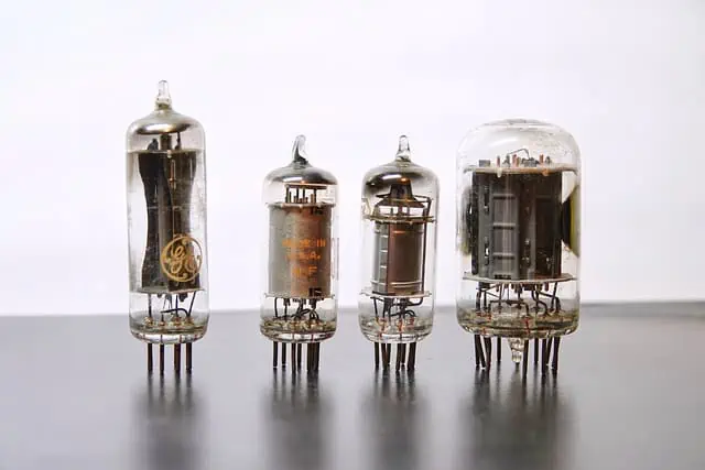
Tube amps were the original amps. Technically speaking, this technology is outdated. These amps produce sound via vacuum tubes, but more on that later. The other newer types of amps are lighter and often have more features. But tube amps have that classic warm tone and smooth overdrive that so many guitarists enjoy. They also have a somewhat inconsistent tone that gives the sound character.
And so, they are still popular, especially for rock and metal. Because of this, they’re often more expensive, however. Still, for the tonal benefits, forking out the cash and lugging around these amps is worth it.
Pros:
- Warm tone
- Great sounding overdrive
- Easy to use
Cons:
- Expensive
- Limited in tonal variety
- Heavy
- Prone to damage and burnout
- Generally only sound good at high volumes
- Tubes need to be replaced around every 18-24 months
How Tube Amps Work
Disclaimer: Tube amps have capacitors that store lethal voltages, even when the amp is off. We’re talking between 500 and 700 volts. So don’t poke around in it unless you have been trained to do so. I’m going to go out on a limb and guess you aren’t if you’re reading this article.
The Simple Explanation with Some Electronics Jargon Chucked In
The signal from the guitar pickups enter the amp, going through the preamp section first. Here the signal gets boosted. Turning your EQ knobs will cut or boost certain frequencies. Turning the volume knob either boosts or diminishes the signal, and sends it through to the power section. In the power section, the signal is amplified and adjusted so that the signal can be played through a speaker.
Tube amps contain valves, or vacuum tubes (aka thermionic valves). These tubes contain cathodes (aka metal filaments), and they work with heat. The cathodes become hot thanks to the cathode heaters, you’ll notice that they glow orange. This heat causes the electrons to rise off of the cathode and be caught by what’s called an anode (aka plate). It attracts those electrons over the vacuum between the cathode and anode. This process generates a current. This would be the audio signal.
Then you have rectifier tubes, or valves (aka diodes). These tubes contain two diodes next to each other which rectify the AC current (alternating current) that is being generated by the vacuum tubes. This means that the AC current is rectified so that it flows in the same direction. So not quite DC current (direct current) which only ever flows in one direction, since audio signal is AC, but at least the AC won’t reverse direction as it tends to do.
Filter capacitors then send this current as DC to the anodes in the amplifier valves (or triodes) at various voltages. This is known as the HT line (high tension line). You’ll find that some tube amps have HT fuses as a safety measure. Should any of the valves take in too high a voltage, the fuses will blow and stop that process.
Amplifier valves are called triodes because they have a cathode, a control grid, and an anode. The audio signal enters the valve and hits the control grid. The cathode, as with the first valve, is hot and releases electrons. This current is limited by the control grid and is taken up by the anode which releases a much larger signal. Thus, the signal is amplified and will go through to the speaker.
The harder you push the amp, the more distortion you get. But be careful, the tubes are prone to burnout. Be sure that if you have an amplifier head, that the speakers you use to form your stack matches the impedance of the amp to prevent damage to the amp and to make your guitar sound awesome.
The Preamp Stage- More In Depth
As the signal from the guitar enters the amp, a resistor sets the impedance to ensure that the voltage is consistent and doesn’t drop. The signal is sent to amplifier valves which are surrounded by more resistors to control the frequency response and the bias (the bias is how much voltage the amplifier valve needs to function). Some valve amps have more than one preamp circuit.
Adjusting the gain knob changes how much signal goes into the rest of the amp circuitry. In the case where there is a second preamp (or more), the signal will go through to that circuit as with the first, but the signal will be amplified even more. This gives more variety to the distortion and overdrive. The EQ knobs will adjust the frequency response via resistors, capacitors (store electricity), and potentiometers (resistors that divide the voltage).
The preamp also contains a triode known as a phase splitter, which yes, does amplify the signal, but also splits the signal into two copies and then alters them to flow in opposite directions. A phase splitter valve with more headroom allows for a cleaner sound, while more distortion is added by one with less headroom. The phase splitter, while situated in the preamp section of the amp, actually drives the signal towards the output section. The master volume then further increases or decreases the signal and sends it to the power section.
The Power Stage
The power section contains four amplifier valves, two on each side connected to their control grids, one handling more of the positive signal, and the other pair handling more of the negative signal. These valves receive the signal from the preamp and sends out identical, but phase inverted copies of this signal.
They work in a push-pull way, with the valves switching so that first one set conducts the brunt of the signal, and then the other set does. This happens constantly thanks to the signal voltage being inverted by the phase splitter in the preamp section.
Depending on the amp, they will work in either class A (where the signal waves will totally overlap for a linear response, so both pairs of valves are operating at the same time all the time) or class AB (where part of the signal overlaps, so one pair shuts off halfway between the cycle and then on again halfway through the other half of the cycle), or a bit of both. Class B, for comparison, is where only one set of valves operate at a time, but this causes a gap in the signal and produces what is called crossover distortion, which is undesirable noise.
It’s safe to say that most amps work in a bit of both. Class A is inefficient compared to class AB even though it produces great tone. That’s because it generates a lot of heat and that is wasted power. The power to volume ratio isn’t good. What you’ll find is that a lot of tube amps will operate in class A when quieter and then class AB when the amp is being driven harder to maximize the power.
This particular setup is more efficient and allows for less noise, giving you distortion and overdrive, depending on how hard you push the amp, where and when you really want it.
The plates in the amplifier valves connect to the coil of the output transformer.
The Output Stage
The output transformer does two things. Firstly, the output transformer delivers high voltage to the anodes in the amplifier valves. Secondly, it acts as the interface between the power amp and the speaker, working to regulate the impedance of the output valves to match that of the speaker. This prevents loss of power, audio, and damage to the amp.
Impedance changes with the changes in voltage and currency, that in an amp, translate to frequencies we can hear. The output transformer actively works to keep the impedance consistent for the speaker by raising and lowering it’s output voltage.
I reiterate, make sure the speakers in your stack match the impedance of the amp. If you connect a speaker with too high an impedance, it will drive the voltage too high and cause damage within the amp. If you connect no cabinet, the output transformer will burn itself out trying to match the impedance which it sees as open-ended. In effect, trying to go to infinity and beyond, but not being able to handle it. A bit like Icarus for those of you into Greek mythology.
On the other hand, a speaker with too low an impedance will cause the output transformer to lower the voltage so much, that it goes into cold bias. No damage will be caused, but it won’t sound good at all.
Solid State Amps
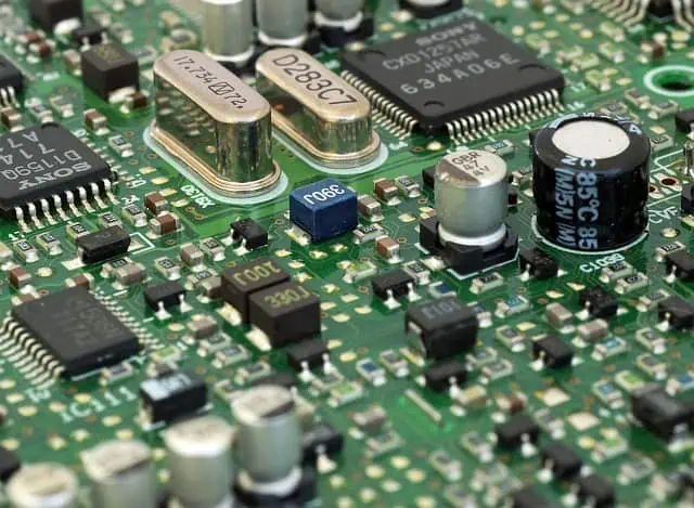
The solid state amp came about when transistors were developed. As you might imagine, comparing transistors to the vacuum tubes, these amps are lighter, and smaller, although you can achieve huge volume depending on the wattage of the amp. These amps are cheaper to produce and are easy to find. They’re also a lot more resilient. Another plus, they require a lot less power to work.
That said, when they were first produced, many guitarists still preferred the tube amps, seeing the solid state amps as cold and even sterile. But for genres that require clean guitar tones, like jazz, funk, and pop, they do well. Technology has improved over the decades, and now you can also get pretty good distortion and overdrive too.
Pros:
- More affordable
- Lighter
- More variety when it comes to tone
- Sound great clean
- Do distortion and overdrive well, provided there’s enough headroom
- Requires less electricity to work
Cons:
- If you love the tube amp sound, solid state amps struggle to compete
- Still not as much variety as combo amps
- Distortion in comparison to tube amps may sound lacking on cheaper amps
How Solid State Amps Work- The Simple Explanation
Just as with tube amps, the signal from the pickups enter the amp at the preamp section. But in this case, transistors boost the signal. Various effects applied via the knobs adjust the electronics inside, altering the voltage and resistance or phase splitting to get effects like delay and reverb. The volume further boosts the signal going through to the power section. Here the signal is amplified and the current modified and sent through to the speakers.
Solid State Amplifiers- An In Depth Look at Semiconductors and Rectifiers
Solid state amps are powered by transistors made of semiconductor material. Solid state amps are called that since the flow of current occurs in a solid state within semiconductors. The electrons flow through solid silicone crystals. This happens because of the interaction between atoms and the silicone lattice within the semiconductor.
Semiconductors are referred to as “semi”conductors because they fall halfway between conductors and insulators. Silicone is typically used in insulating materials, for example, glass. That said, silicone has the right amount of valence electrons to form a stable crystal structure. If you look on the periodic table, it’s a group 4 element. All group 4 elements share this characteristic.
It doesn’t do this in all states. Pure silicone at room temperature, for example, works as an insulator rather than a conductor. Elements with slightly too few (group 3 on the periodic table) or too many valence electrons (group 5 on the periodic table) (like boron, gallium, arsenic and phosphorus) are added to create impurities. This creates holes that electrons want to fill.
P-type semiconductors are formed when grouping silicone with an element that has too few electrons. N-type semiconductors are formed when grouping silicone with an element that has too many electrons. In this case, the additional electrons move around within the lattice. Using these two semiconductors together causes a boundary between the two called a P-N junction. Electrons from the N-type semiconductors will move over to the P-type semiconductors to fill in the holes. This causes a depletion layer in the middle, which then acts as an insulator.
A forward voltage will cause electrons and holes to move towards this depletion layer, making it narrower. If enough voltage is applied, this depletion layer will disappear, and the semiconductors become conductors, allowing the electrons to flow freely across. This is known as forward bias.
The opposite can be done too, using a reverse voltage. This will widen the depletion layer and give it infinite resistance. This is known as reverse bias.
This P-N junction is called a diode. As you may recall from the tube amp section, a diode allows the current to flow in only one direction. This is used as a rectifier which prevents the current from dropping, and as mentioned in the tube amp section, is standard technology even in a tube amp for this purpose.
The Preamp Stage- More In Depth
As the signal from the guitar enters the amp, the preamp boosts and modifies that signal. As with tube amps, transistors are set up as gain stages, usually two. The signal is enlarged and the impedance is lowered. These gain stages will also eliminate electromagnetic noise (EMF) for a cleaner signal.
This is done via a JFET (Junction Field Effect Transistors) or MOSFET (Metal Oxide Silicon Field Effect Transistors). Often MOSFETs are used these days because they have greater resistance than JFETs.
Preamps
We’ll look at the preamp from the perspective of using JFETs.
JFETs are like the semiconductors mentioned before, but with a third terminal (gate) added. Essentially, they now behave like triodes. A JFET has a source and a drain with a gate terminal in the middle attached to the P-type material. With a potential difference (the amount of energy used to move a positive charge without acceleration between two points), so essentially, applying a current, said current flows from the source, across the N-type semiconductor, and out through the drain.
When reverse bias is applied to the P-type semiconductors, it causes the depletion layer to expand. The addition of an audio signal causes the depletion layer to expand and contract. This process creates an enlarged copy of the signal.
Whatever controls you turn on the outside, have circuitry inside that alter the voltage and impedance to produce different sounds This signal is then sent through to the power amp.
The Power Stage- More In Depth
For this section, we’ll do it from the perspective of using MOSFETs. The power amp circuit works by way of two MOSFETs, connected in series. In the process of amplifying the signal further, heat is generated. Heat damages transistors and most will shut down at a certain temperature. So the MOSFETs are connected to a heat-sink (an aluminium radiator) to dissipate the heat.
The two MOSFETs are connected as PNP and NPN, this creates the signal to flow in with opposite waves, albeit in the same direction. They are connected to a chassis that is connected to each power supply (there are two). They will alternate the current going through. In fact, modern solid state amps are connected in class AB. This means that this push-pull way of working creates a linear amplification response which eliminates most, if not all, the crossover distortion that made solid state amps very noisy in the past.
If you have more than one speaker, they have to be connected to the correct terminal to ensure that the cones move in tandem. If you had a look, you would see that the polarity mark indicating a positive charge (+) is connected to the positive terminal of the power supply. In the case of having one speaker only, it doesn’t matter which way it’s connected to the terminal. The speaker will connect to each power supply in turn, a safety measure to ensure the speaker won’t be damaged.
Another major difference between tube amps and solid state amps, is that solid state amps don’t need an output transformer. All in all, you end up with a far more energy efficient and lighter amp. It’s also the lack of all that iron, that makes those that prefer tube amps, feel that solid state amps are cold and lack character. Still, a good quality modern solid state amp produces great sound in its own way, and consistently too, no matter the volume. And, unlike tube amps, will work for years without ever having to be serviced.
Modeling Amps (a.k.a Digital Amps)
Modelling amps are technically solid state amps, but technology has allowed for them to be able to have multiple amp models. This means that you can turn a knob or push a button to select a tone that sounds like specific amps both solid state and tube, alike. While earlier amps did sound like a crappy imitation of these amps, technology has improved. Now, the settings on the modelling amps sound pretty much indistinguishable. Of course, the better the quality of the amp, the more realistic the sound.
Pros:
- Large variety of tones
- Lighter than even regular solid state amps
- Generally cheaper
Cons:
- Some modelling amps may struggle to accurately reproduce tube amps
- Older modelling amps don’t sound good
Hybrid Amps
Hybrid amps are a mix of modelling and tube amps. If you looked inside, you’d see vacuum tubes and transistors. The idea is that you get the best of both worlds. The true warmth, smooth overdrive, and character from the tube amps, and the variety of the modelling amp. There are some that do this very well.
But as most guitarist can attest, the other three types of amps are more popular by far, generally because they do a much better job. For those who like a modelling amp, but find the tube amp model settings lacking, a hybrid is a good option.
Pros:
- Tube amp sound is authentic
- Provides a large variety of tones
- Eliminates or reduces the need to have two amps (modelling and tube)
Cons:
- While cheaper than a tube amp, they’re more expensive than modelling amps
- They’re heavier than modelling amps because of the tubes
- The modelling amp part of the hybrid amp isn’t always as good as a modelling amp
What is a Combo Amp?
You may be wondering about the other types of amps that you’ve come across. I didn’t even mention practice amps, which are just small amps that sound good when quiet, and yes, you can get small tube amps too. And of course, there are Bluetooth amps too. But these are all just different sizes of the above-mentioned amps, or those amps with extra capability.
Combo amps, however, aren’t a type of amp like the above amps. Rather, they’re what a lot of these amps are, the head and speakers in one cabinet. That means the actual amp and the speaker is one unit. The alternative is stacks. You’ll have an amplifier head like the Bugera G5, and separately, you have speakers that you stack. This works great for stage performances where you need a lot of volume.
Conclusion
Now you have an overview of how amps work. If you’re into electronics, there are even more in-depth explanations out there. But for those who want to satisfy their curiosity through a simple overview, these explanations give you that. Technology is amazing and how far it’s come is just as crazy.
If you like the older technology, you can find improved modern tube amps that sound even better than the old technology. If you prefer the modern stuff, solid state amps have come a long way, and the better quality you get, the better the sound. Check out these tube and solid state amps if you’re looking to buy.
Happy jamming!


